Features

Applications

PackagingPriceQuantity
Box of 10 AFM Probes
280,00 
Box of 20 AFM Probes
500,00 
Box of 50 AFM Probes
1150,00 
Estimated total : 0,00 
→ You can generate a quote directly from the cart page
Order code : LS0P1_Si-Si-30

Specifications

Parameter
Unit
Nominal
Range
Frequency
kHz
40
20-60
Spring constant
N/m
0.1
0.05-0.5
Tip height
µm
30
15-50
Tip apex radius
nm
7
2-10
Tip side angle
.
7
+/- 0.5
Tip-cantilever angle
.
7
+/- 0.5
Cantilever length L
µm
80
+/- 1
Cantilever Width W
µm
20
+/- 1
Cantilever Thickness T
µm
0.5
+/- 0.5
Cantilever backside coating
.
None
.
Tip side coating
.
None
.
Tip and cantilever material
p-doped
.
.
Chip dimensions
nm
3.4
.

Cantilever & tip details

Probe overview

Special packaging

Spectroscopy and images with SNOM tips that have been packaged in standard AFM Gel-Pak boxes can lead to artifacts in the optical response. This is due to contamination of the tip by a few molecules of the gel. Vmicro has developed a back-end process with special decontamination and storage in a metal box. You can select this feature as an option when selecting your reference.


Nano-FTIR spectra normalized and obtained at the SMIS beamline at Synchrotron SOLEIL. (Courtesy F. Borondics – G. Németh)

Features

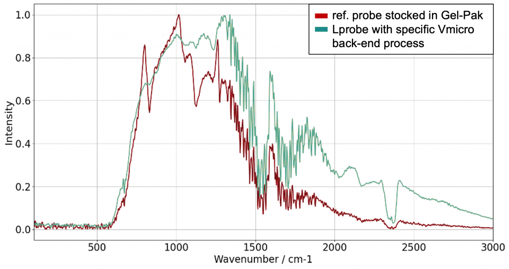
Lprobes are based on a new MEMS patented technology enabling improvements as compared to silicon AFM cantilevers with tip fabricated using mainstream processes developed in the 90’s.

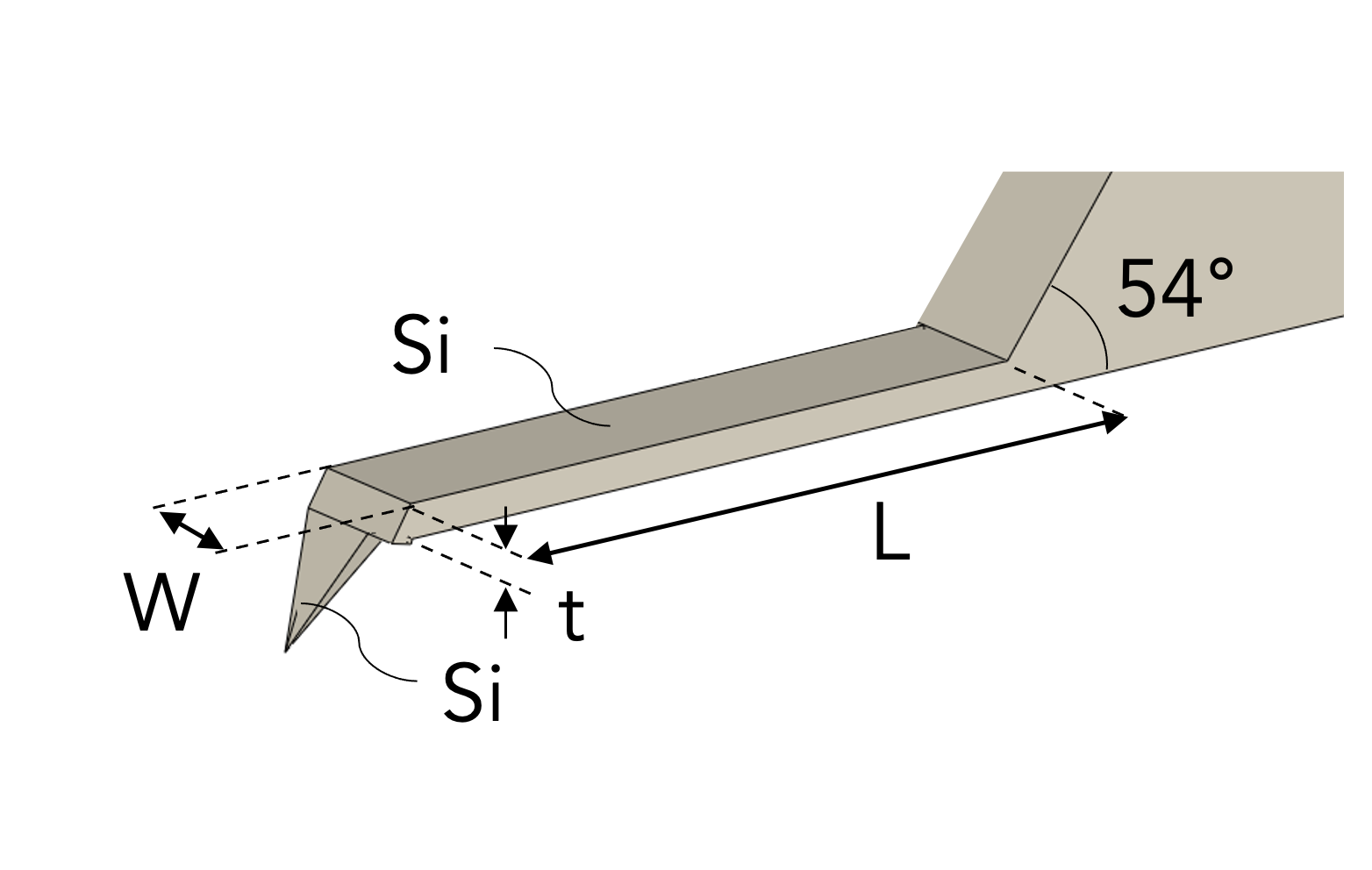
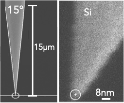
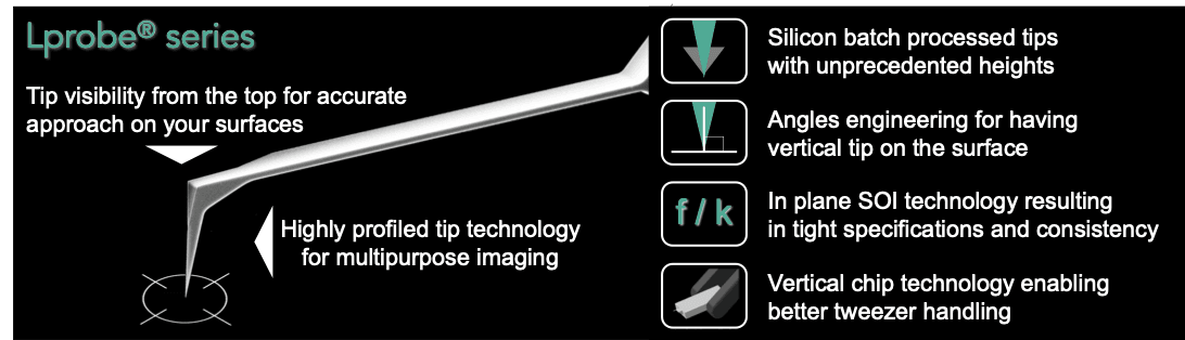
Vmicro In-plane technology enables full batch fabrication of tips with high lengths, low masses and high aspect ratios not only close to apex.

Both cantilever and tip are made of highly doped monocrystalline silicon.

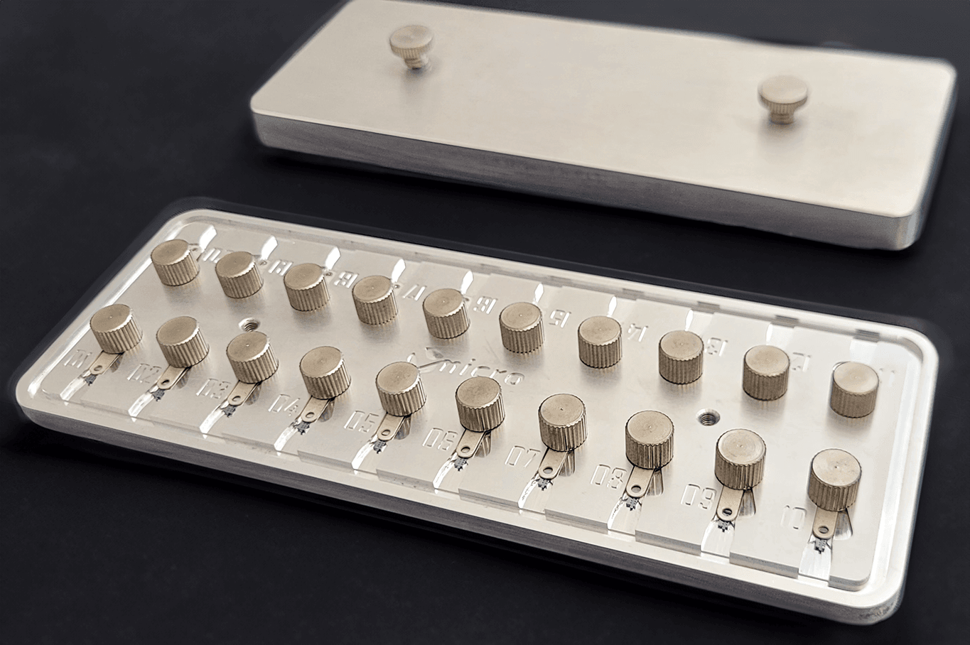
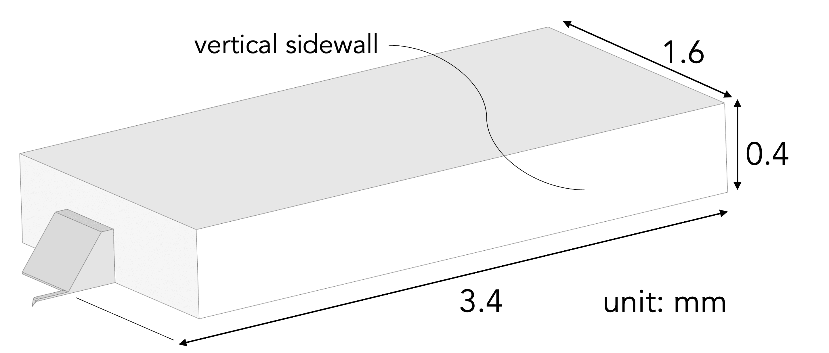
Lprobes are compatible with most SPMs. Our chip is designed with vertical sidewalls that enable safer handling with tweezers.

Probe parameters

Resonant frequency (kHz)
Nom.
Typical range
40
20-60
Spring constant (N/m)
Nom.
Typical range
0.1
0.05-0.5

Cantilever

Cantilever (nominal values)
L (µm)
W (µm)
t (µm)
80
20
0.5
Coating
Cantilever back side
None
Tip side
None

Highly conductive silicon, uncoated, tip and cantilever.

Tip

Tip dimensions
Nom.
Typical range
Tip height T (µm)
30
15-50
7
2-10
  • Tilted tip design
    Compensates for the AFM head’s mounting angle, ensuring accurate data on diverse sample surfaces.
  • Tip height >30 µm
    Enables imaging of deeper or difficult-to-access sample regions.
  • Half-cone angle < 10° over the last 10 µm 
    Minimizes tip-sample convolution, ensuring more accurate morphological measurements.
  • Guaranteed tip radius < 10 nm
    Provides reliable resolution for advanced AFM applications.